We know that the data that is sent across the medium is encrypted to keep the data secure. So, 802.11i Standard specifies the CCMP, which provides data confidentiality, authentication, integrity, and replay protection.
CCMP is mandatory for RSN compliance. Here we have two things that we need to know how CCMP provides security to the data transmitted over the air.
In this post we will learn about the CCMP encryption, decryption and then we will test some input data and we will decrypt the data and verify whether the expected results are coming. Please note that it is little difficult to understand this CCMP encryption and decryption process.
- Encryption
- CCM Uses CTR (Counter Mode) for data Confidentiality.
- It uses Block Cipher.
2. Authentication and Integrity.
- CBC-MAC is used for authentication and integrity.
- CBC-MAC is a technique for constructing a message authentication code from a block cipher.
- The message is encrypted with some block cipher algorithm in CBC mode to create a chain of blocks such that each block depends on the proper encryption of the previous block.
AES processing used within CCMP uses AES with a 128-bit key, 128-bit block size and 8 Byte MIC. It is same for both WPA2 , and WPA3 Personal. WPA3 Enterprise will use 192-bit session key with GCMP-256 encryption.
In CCMP Encryption and Authentication/Integrity will be executed, And finally We generate the encrypted data , and we will add 8 Byte MIC at the end of the encrypted data as per the 802.11i Specification.
Observe the below diagram and check that two programs CBC-MAC generates the MIC and CTR Mode uses to encrypt the Data.
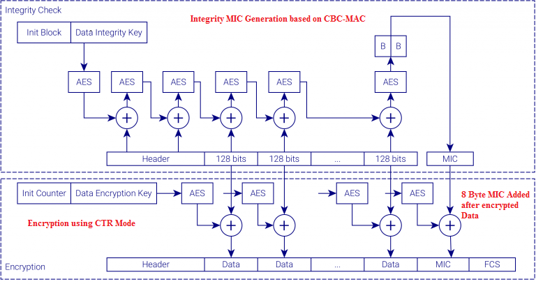
CCMP Encryption Encapsulation
Observe the below figure to know what are the inputs that CCMP program Expects as a input to generate the encrypted data.
The Inputs that are required to generate the encrypted Data are:
- TK (Temporal Key)
- AAD (Additional Authentication Data)
- Nonce
- Plaintext Data

Below are the steps involved in encrypting the MPDU in CCMP.
- Increment the PN, to obtain a fresh PN for each MPDU, so that the PN never repeats for the same temporal key.
- Use the fields in the MPDU header to construct the additional authentication data (AAD) for CCM. The CCM algorithm provides integrity protection for the fields included in the AAD.
- Construct the CCM Nonce block from the PN, A2, and the Priority field of the MPDU where A2 is MPDU Address 2.
- Place the new PN and the key identifier into the 8-octet CCMP header.
- Use the temporal key, AAD, nonce, and MPDU data to form the cipher text and MIC. This step is known as CCM originator processing.
- Form the encrypted MPDU by combining the original MPDU header, the CCMP header, the encrypted data and MIC. (See the Below Section).
CCMP MPDU Format
1 Constructing CCMP Header
Now lets decode the CCMP header and then the do a wireshark example to decode the CCMP header.

- CCMP processing expands the original MPDU size by 16 octets.
- 8 octets for the CCMP Header field and 8 octets for the MIC field.
- The CCMP Header field is constructed from the PN, ExtIV, and Key ID subfields as shown in the Figure 3.
- PN is a 48-bit PN represented as an array of 6 octets. PN5 is the most significant octet of the PN, and PN0 is the least significant.
- The ExtIV subfield (bit 5) of the Key ID octet signals that the CCMP
- Header field, The ExtIV bit (bit 5) is always set to 1 for CCMP.
- Bits 6–7 of the Key ID octet are for the Key ID subfield.
- The reserved bits shall be set to 0 and shall be ignored on reception.
CCMP Header Decoding
Now lets do a example to decode the 8 octet CCMP header. And we will decode Packet Number and then Ext IV and then Key ID. Knowing how to Decode the Packet Numbers properly will be useful if you are executing a CCMP program to verify the encrypted data.
we will take the below example first and then we will move to the wireshark example to decode CCMP Header.
Assume that in our example CCMP header is given as below.
In our Example, CCMP Header = ea 97 00 a0 ba cb f3 31
In the above CCMP header PN (Packet Number) = (0x31F3CBBA97EA) Based on the diagram shown the Figure 3. And PN is stored across 6 octets in CCMP header.
And we are left with 00 a0 from the above example , so here 00 is reserved.
And we are left with 0xa0, this is the Ext IV and KEY ID. So, here we will decode that 0xa0.
So, now we will convert the 0xa0 to binary, Observe the below binary data for 0xa0. Now we will decode the KEY ID Octet. Read the bits from the LSB.
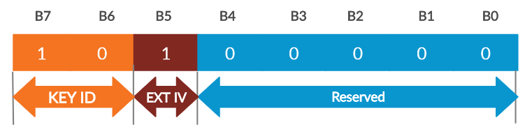
So, Here the KEY ID value = 10 [Decimal Equivalent to 2]
EXT IV =1 [It will be set to 1 , for CCMP Encrypted data]
So, CCMP Header = ea 97 00 a0 ba cb f3 31
After Decoding, the values will look like this
PN = (0x31F3CBBA97EA)
KEY ID = 2
EXT IV = 1 [For CCMP]
Now we will try to decode the CCMP header from wireshark.
Observe the below CCMP header and decode the values as discussed above.

Decoding CCMP header from wiresahrk
PN = 0x000000000003
KEY ID = 0
Ext IV=1
2 Constructing AAD [Additional Authentication Data]
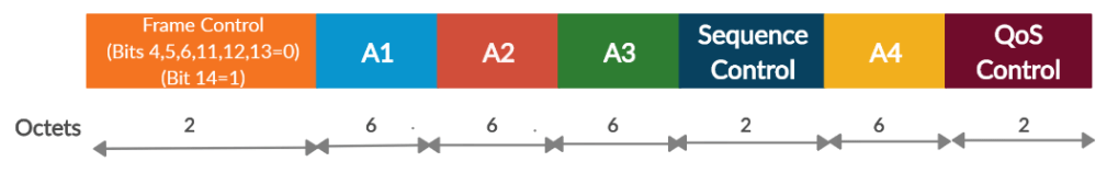
Now we will learn about the constructing of the Additional Authentication Data. The format of AAD is given below. The AAD is constructed from the MPDU header. Observe the below figure.
The length of the AAD varies depending on the presence or absence of the QC and A4 fields. Check the length of the AAD from the below Table.

Rules Involved in Constructing the AAD:
The AAD does not include the header Duration field. because the Duration field value can change due to normal IEEE 802.11 operation (e.g., a rate change during retransmission). For similar reasons, several subfields in the Frame Control field are masked to 0.
If you want to learn about how to generate the AAD based on the rules defined in the standard, then go through the below rules and try to generate the Muted Header from the MAC Header. If you are facing any difficultly in understanding this section , then skip this section, and just know that the AAD is generated from the MAC header.
Below are the rules to generate the AAD:
- FC – MPDU Frame Control field, with
- Subtype bits (bits 4 5 6) masked to 0
- Retry bit (bit 11) masked to 0
- PwrMgt bit (bit 12) masked to 0
- MoreData bit (bit 13) masked to 0
- Protected Frame bit (bit 14) always set to 1
- A1 – MPDU Address 1 field.
- A2 – MPDU Address 2 field.
- A3 – MPDU Address 3 field.
- SC – MPDU Sequence Control field, with the Sequence Number subfield (bits 4–15 of the Sequence Control field) masked to 0. The Fragment Number subfield is not modified.
- A4 – MPDU Address field, if present in the MPDU.
- QC – QoS Control field, if present, a 2-octet field that includes the MSDU priority. The QC TID is used in the construction of the AAD, and the remaining QC fields are set to 0 for the AAD calculation (bits 4 to 15 are set to 0).
Below I am showing the example MAC header , and by using the MAC header we will be generating the Muted Header which is AAD.
Below is the example that is being shown, we have to generate the Muted MAC header based on the Rules above.
FC=0x0848
Duration = 0xc32c
A1 = 0f-d2-e1-28-a5-7c
A2 = 50-30-f1-84-44-08
A3 = ab-ae-a5-b8-fc-ba
SC = 0x8033
Based on the above data , now we will construct the MAC header
802.11 Header = 08 48 c3 2c 0f d2 e1 28 a5 7c 50 30 f1 84 44 08 ab ae a5 b8 fc ba 80 33
If we solve the above 802.11 Header , then the muted header will be
Muted Header = 08 40 0f d2 e1 28 a5 7c 50 30 f1 84 44 08 ab ae a5 b8 fc ba 00 00
Now we will just solve the Frame Control Field (i.e first 2 Bytes of MAC header based on the rules above. Remaining all the bytes you can solve based on the above rules. So, in the above example QC Field and A4 field is absent so the length of the AAD = 22.
So, Here we will take the first 2 Bytes of MAC header = 0x0848
so, the binary representation of the above data is shown in the below Figure 6. Read the bits from the LSB.
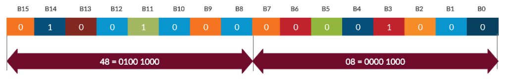
Now , we will follow the rules to generate the muted Frame Control.
In the Muted Header the values will be as follows in the frame control.
- Subtype bits (bits 4 5 6) masked to 0
- Retry bit (bit 11) masked to 0
- PwrMgt bit (bit 12) masked to 0
- MoreData bit (bit 13) masked to 0
- Protected Frame bit (bit 14) always set to 1
Now we will follow the rules and replace the bits properly. Read the bits from the LSB.

So ,the result muted Frame Control is “0x0840”, and it matches with our value. Remaining values you can do it by yourself. Just follow the rules if you want to generate.
3 Construct Nonce
The below diagram shows the Construction of a Nonce.
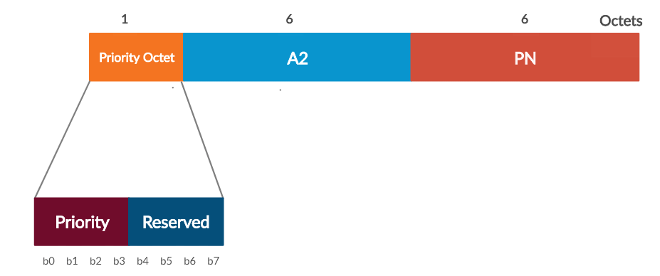
Rules to Follow to construct the Nonce
- The Priority Octet field shall be set to the fixed value 0 (0x00) when there is no QC field present in the MPDU header.
- When the QC field is present, bits 0 to 3 of the Priority Octet field shall be set to the value of the QC TID (bits 0 to 3 of the QC field). Bits 4 to 7 of the Proirity Octet field are reserved and shall be set to 0.
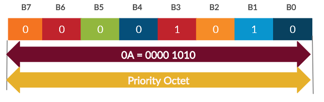
We will see the example here to calculate the Priority Field if the QC field is present.
Now lets take the example QC Field as = 0x000a.

So, the resulting Priority Field is going to be 0a based on the above rule. You can do that by checking the QC Field and properly decoding the values.
As per the rules above , in the Priority Field the first 4 bits will be the TID value of the QC Field, and the remaining bits are reserved. So, the Priority Octet is shown in the below Figure. Read Bits from LSB.
- A2 = MPDU address A2 field
- PN = Packet Number
Below are the values given
Priority Octet= 0a
A2 = ca-3f-3a-ae-60-c4
PN = 0xCEFD996ECCDD
Then the CCM Nonce is
CCM Nonce= 0a ca 3f 3a ae 60 c4 ce fd 99 6e cc dd
This is about the CCMP encryption, and we have learnt about how the inputs to the CCMP gets generated.
Now we will see the CCMP decapsulation.
CCMP Decapsulation
The below figure shows the decapsulation of a CCMP encrypted data.
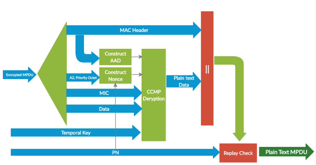
Decapsulation process of CCMP follows the below steps:
- The encrypted MPDU is parsed to construct the AAD and nonce values.
- The AAD is formed from the MPDU header of the encrypted MPDU.
- The Nonce value is constructed from the A2, PN, and Priority Octet fields.
- The MIC is extracted for use in the CCM integrity checking.
- The CCM recipient processing uses the temporal key, AAD, nonce, MIC, and MPDU cipher text data to recover the MPDU plaintext data as well as to check the integrity of the AAD and MPDU plaintext data.
- The received MPDU header and the MPDU plaintext data from the CCM recipient processing may be concatenated to form a plaintext MPDU.
- The decryption processing prevents replay of MPDUs by validating that the PN in the MPDU is greater than the replay counter maintained for the session.
Input to the CCMP decryption Process:
We have already discussed about these inputs in the Encryption process.
Below are the 4 inputs to the CCMP decryption process.
- Key: the temporal key (16 octets).
- Nonce: the nonce (13 octets)
- Encrypted frame body: the encrypted frame body from the received MPDU. The encrypted frame body includes an 8-octet MIC.
- AAD: the AAD (22–30 octets)
The decapsulation process succeeds when the calculated MIC matches the MIC value obtained from decrypting the received encrypted MPDU. The original MPDU header is concatenated with the plaintext data resulting from the successful CCM recipient processing to create the plaintext MPDU.
Replay Detection
The receiver shall discard MSDUs whose constituent MPDU PN values are not sequential. A receiver shall discard any MPDU that is received with its PN less than or equal to the replay counter.
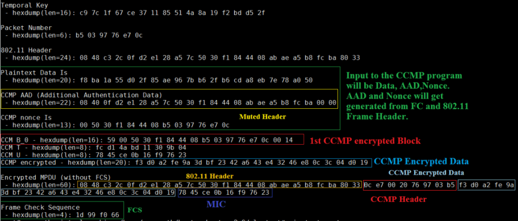
CCMP Encryption Example
Observe the below example to verify the CCMP encryption/Decryption. I have used some test vector and we will verify the results by sending the below input to the CCMP program.

Now we will send the input to the CCMP program and then we will verify the results that are being shown in the above figure.
The input to the CCMP program will be.
- Data (FrameControl + Plain Data)
- Plain Packet Number
- TK
Remaining Nonce , AAD CCMP headers will get constructed based on the PN, Frame control and the rules that we have discussed earlier in the post.
Now we ill run the program and we will check the results that got generated from and we will compare the results that are sown above.
Observe the encrypted data in the below figure. And compare the results with the data that is being shown in the Figure 13. All the data matches with the output.
The same way we can decrypt the encrypted as well. This is all about CCMP encryption and decryption.
In the later posts we will do any real time example and then we will verify the CCMP encryption and decryption in the wireshark.
