In PART-1 we have learnt till P2P GO Negotiation Phase, and now we will look into the Group Formation Procedure. You can find the part-1 from the below link https://praneethwifi.wordpress.com/2019/10/31/p2p-group-formation-procedures-negotiation-method-part-1/

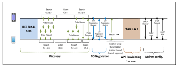
Now We will learn about Phase-1 and Phase-2. See the below diagram also to make the things little clear about Negotiation Method.
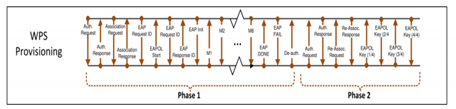
Now , we will learn about the WPS provisioning and we will see the frame exchanges involved in the Group Formation. See the below for WPS Provisioning and the frames that will be exchanged during the WPS Provisioning phase.
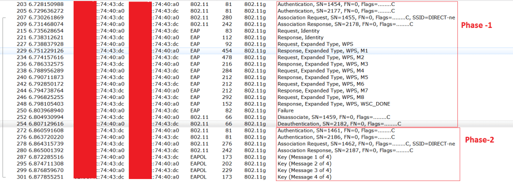
We will see the sniffer capture to see about the Phase 1 and Phase 2 of the group formation. See the below capture to observe the phase-1 and phase-2 of the P2P Group formation using PBC method.
I have filtered only the required frames in the wireshark. The below frames exactly matches with the Figure 3.
Group Formation has a phase called Provisioning that uses wifi Simple configuration. Wi-Fi Simple Configuration may take up to two minutes to complete, due to waiting for user input. Since Group Formation may need to execute multiple times, such a delay is unacceptable.
A P2P Device shall obtain any information required to execute Provisioning in advance of Group Formation, which includes information such as a PIN that is obtained from a user. A P2P Device shall take no more than fifteen seconds to complete Group Formation.
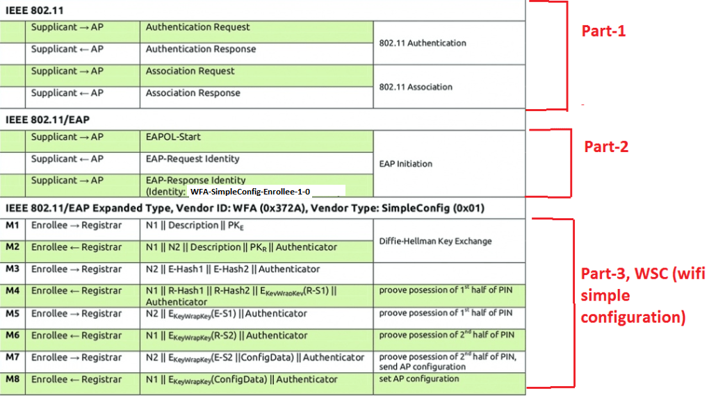
See the below image to know the details in depth about the P2P Group Formation Procedure flow.
Phase-1
Part-1 of Group Formation Procedure
In the Figure 5 , Part-1 is basic authentication request and authentication response frames , we see these frames in normal WiFi Association as well, so there is nothing new about these frames in WiFi Direct as well. These frames are similar to what we see in the normal association.
Part-2 of Group Formation Procedure
In part-2 we do see the EAP authentication process, and follow the steps below, based on the Figure 5.
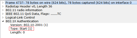
1) Supplicant(Peer Device) will send the EAPOL-Start frame to the AP (GO). I have not seen this frame in the capture. I have observed that GO is directly initiating the process. If that message is being sent then we will see the below info in the sniffer capture.
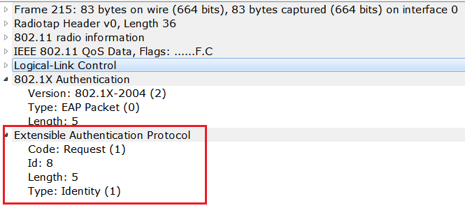
2) Now the GO will send the Request Identity to the Peer device and observe the below capture to check this frame.
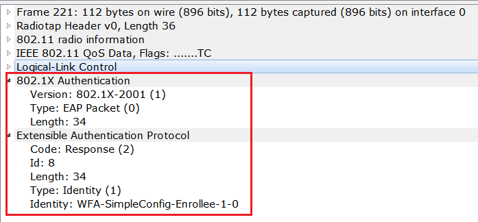
3) Now Peer device will send the response identity to the GO. And Peer device is sending Identiy as “WFA-SimpleConfig-Enrollee-1-0” , and the GO is the Registrar.
Part-3 of Group Formation Procedure (WSC Procedure)
1) Before the M1 Message , AP will send the WSC Start (1) to the Supplicant. Observe the below capture to check this message. See the Request below From the GO.
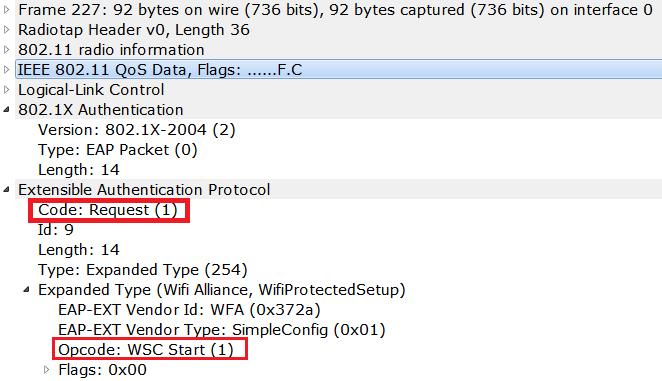
After WSC-START we will see the M1 to M8 messages in the wsc procedure. And in M1 and M2 diffie-helmen key exchange will happen to generate the shared key. Both the Supplicant and GO will exchange the public keys to generate the common shared key. GO and supplicant will not share the private key, they will calculate the shared key using Diffie-Helmen key exchange algorithm.
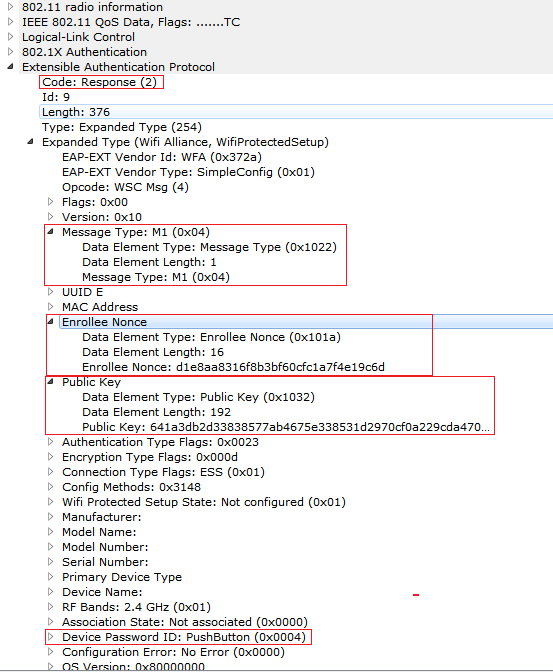
2) See the below sniffer capture to check the M1 message that is being sent from Enrollee(Suppicant) to Registrar(GO), and here public key of the supplicant , and Enrollee Nonce will be sent to the GO. Observe the below capture to check this. Observe the Response from the Supplicant. We are doing the PBC method to form a Group and observe the information in the below sniffer capture.

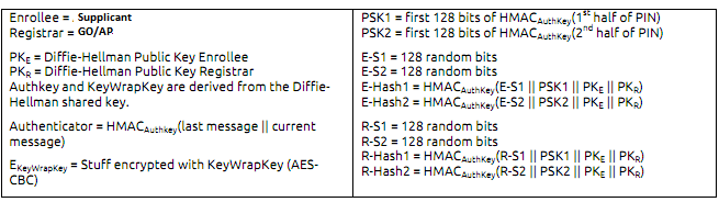
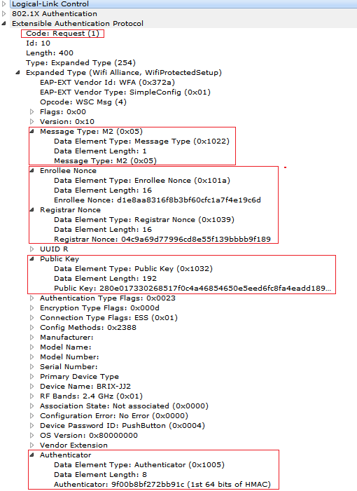
3) Now M2 message is sent from the GO to the Supplicant and observe the Enrollee nonce, Registrar Nonce , Public key of the Registrar(GO) and Authenticator is being sent. Observe the below figure to check how the algorithm will calculate these values.


Observe the below sniffer capture to check the M2 Message. Here Public key of the Registrar is sent to the Enrollee as a part of Diffie-Helmen Key exchange.
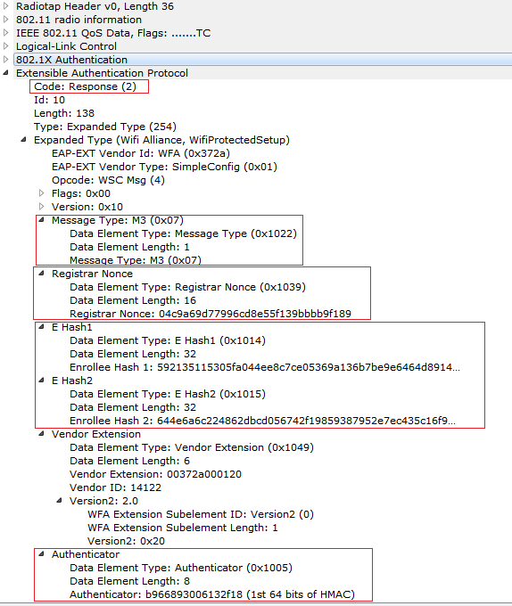
4) Now see the M3 message being sent from the Supplicant to the Registrar. Observe the Figure 7 to know how the algorithm is calculating the E-Hash1 and E-Hash2 values that are being sent in M3 Message.

Observe the below capture to see the M3 Message.
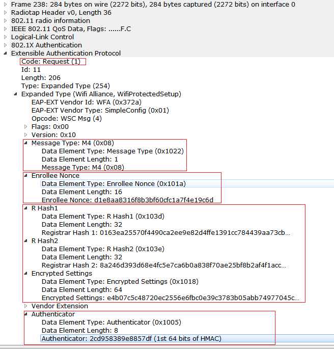
5) Now observe that M4 Message being sent from Registrar to Enrollee. At M4 and M5 Mutual authentication will happen, Registrar has to prove that 1st half of PIN in M4 and Enrollee has to prove the first half of the PIN in the M5. Usually the PIN will be 8 digit number, And if the wrong 1st half PIN is entered then there will not be any messages going after M4 Message. So that we can know that the 1st half of the PIN is incorrect. If the second half of the PIN is wrong then we don’t see any messages going after M6.
But in the PBC method we dont enter any PIN, then the default PIN will be taken and it will be “000000000”.
(Note: The PBC method may also need a Registrar when used in a special case where the PIN is all zeros).

See the below capture to check the M4 in the sniffer capture.
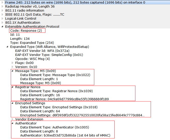
6) Check the M5 Message being sent from the Enrollee to registrar. And observe the sniffer capture for M5. Here Enrollee (supplicant) proves the possession of the 1st half of the PIN with Registrar. So, the mutual authentication of the 1st half f the PIN gets over with this message.

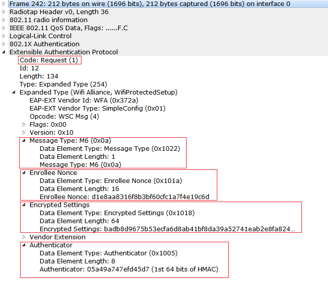
6) Now observe the M6 Message being sent from Registar(GO) to Enrollee, and here Registrar will prove the 2nd half of the PIN with the Enrollee. If there wrong 2nd half of the PIN entered, then there will not be any messages going after M6.

Observe the below capture to check the M6 Message in the sniffer capture.
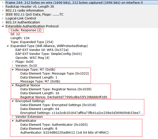
7) Observe M7 Message being sent from the Enrollee (supplicant) to Registrar (GO) , and here Enrollee proves the 2nd half of the PIN and the mutual authentication to prove the 2nd half of the pin ends here.

Observe the sniffer capture for M7 Message.
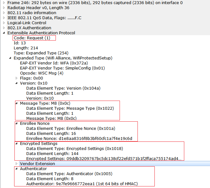
8) Observe that M8 Message is being sent from the Registrar to supplicant and , and in this M8 Message, Security configuration, New Credentials, are being delivered to the Enrollee. Now the Supplicant has to reconnect to the GO using the new credentials.

Observe the below sniffer capture to see the sniffer capture of the M8 Message.
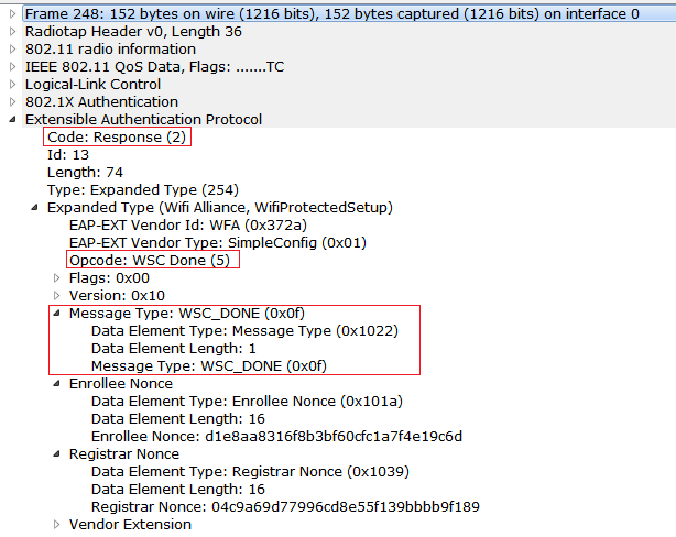
9) Now the Enrollee sends the WSC_DONE to the Registrar and the Wifi Simple configuration will end after this message. Observe the below capture to see this frame.
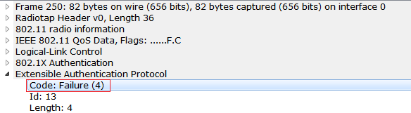
10) Registrar returns an EAP-Fail message to the Enrollee. The Enrollee Then disassociates and reconnects with the credential obtained from the M8 Config data. and the older association was no longer valid.
Observe the EAP-FAIL Message being sent by the Registrar (GO).
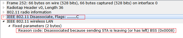
11) Now the supplicant(Enrolle) will disasscoiate and it will send the disassociation frame to the GO(Registrar). Observe the below capture.
12) Now GO( Registrar) will send the Deauthentication frame and then the Supplicant will start the new association with the new credentials that are being sent. Observe the below capture.
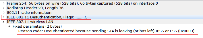
With that message the PHASE-1 of the Group Formation Procedure is finished. Now see the Phase-2 of the Group Formation procedure.
Phase-2
I have written other post about 4-way handshake procedure. Check out the below link.
https://praneethwifi.wordpress.com/2019/11/08/4-way-hand-shake-keys-generation-and-mic-verification/
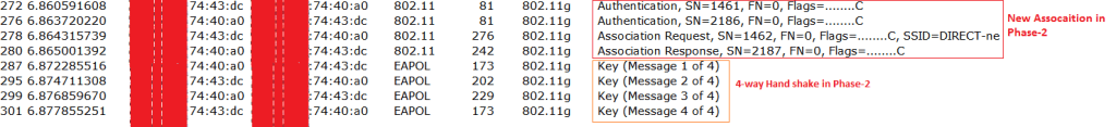
Now observe that Phase-2 of the Group formation procedure and , it is a 4-way hand shake .
4-way hand shake here is same as WPA2-Personal. But the only thing here is that we don’t enter the passphrase. But in the PBC method Credential information is being sent in the M8 Message. So, the 4-way hand shake will generate the PTK, GTK and other required keys from the credential being sent in the M8 Message, here the master key is dynamically created using WPS procedure. Encryption for the data will be done using AES-CCMP method.
See the below capture to check the 4-way hand shake procedure that will be done in the phase-2 of the Group Formation. Also check my other post in detail analysis of 4-way handshake from the below link.
With the 4-way hand shake the group formation procedure has finished. And the Phase-2 is done.
After Phase-2
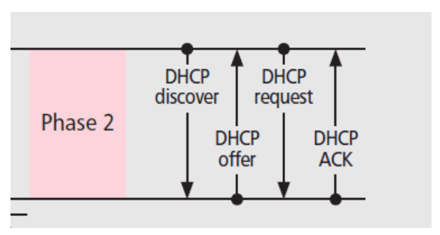
Now the DHCP hand shake i.e DORA Procedure will happen, GO will assign the IP to the GC, and after that Data communication will be started.
Observe the below image to see DHCP procedure that has started after the phase-2, now we don’t see the DHCP handshake in the sniffer , as these messages are encrypted after the 4-way hand shake, we see the encrypted DHCP frames in the sniffer. We need a private key to see the DHCP hand shake.
Observe the below diagram to check the DHCP procedure.
After this Data transfer will happen in between GO and GC. See the below capture to observe DHCP procedure. We can see the DHCP procedure in the wireshark. But we should have the 4-way handshake captured and then we need to enter the either PSK or PASSWORD:SSID in the wireshark to decrypt the Traffic. Observe the below capture to see the DHCP decrypted traffic in the sniffer.
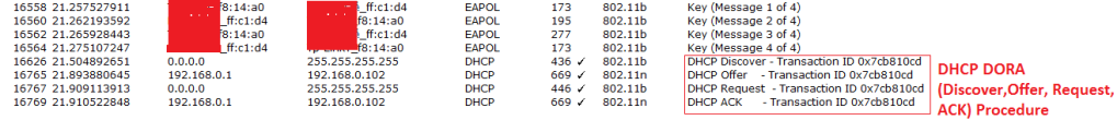
After the DHCP procedure, Data transfer will happen and P2P Uses AES-CCMP encryption by default.
This is all about P2P Negotiation Method.
